A resource for technical documentation. Datasheets, application notes, instruction manuals, books and links to resources are found in the Document Library.
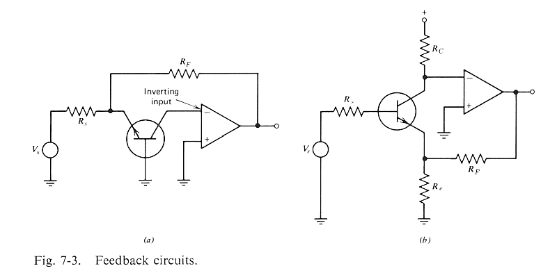
The "op amp around the transistor" "current feedback" circuit shown by Demrow in 1968 https://proaudiodesignforum.com/forum/p ... =12&t=1052 and documented by Motchenbacher and Fitchen in 1973.
This is the single-ended half-circuit of the popular "Cohen" differential style preamp.
I've shared this story before... back in the late 70s I was living about one town away from Bridgeport where Fitchen was teaching at University of Bridgeport. His phone number was in the phone book so I called him. I wanted to pick his brain about a Leach low noise topology that was unusual (he didn't know either). After a nice chat he asked me to contribute to a chapter for his next book... I demurred, I was not an academic (college dropout), but I gather Motchenbacher was also a working design engineer, and Fitchen was the professorial half of the team.
JR
Cancel the "cancel culture", do not support mob hatred.
I had posted that page here elsewhere but I thought it deserved its own thread and index.
Its one of the more practical books and I enjoyed leafing through it again.
You don't see the common base circuit often unless its a mic preamp re-purposed as a bus summing amp or "current input" moving coil phono preamp.
On figure (b) there should be a positive DC potential at the non-inverting op amp input. (Vbias)
(Vcc-Vbias)/Rc = Ic
For your SE model you also need to add a coupling cap in series with Re.
Ie is provided by the op amp.
The common base configuration of figure (a) has always been interesting to me.
It's what you get when you make a summing amp out of a CFB mic preamp like a THAT1510.
ok.
I'm aware of the positive DC potential at the non-inverting input of the amplifier in figure b.
I was able to get something going with a negative DC potential at the non-inverting input of the amplifier in figure a.
This looks like a fun circuit to play with...